Inquiry:

sales@anycoms.com
0755-88868185

Features
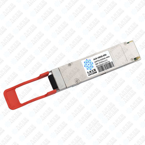
l Compliant to Ethernet 100GBASE-ER4 Lite
l Supports 103.1Gb/s aggregate bit rate
l Transmitter: cooled 4x25Gb/s LAN WDM EML TOSA (1295.56, 1300.05, 1304.58, 1309.14nm)
l Receiver: 4x25Gb/s APD ROSA
l Up to 30km reach for G.652 SMF without FEC
l Up to 40km reach for G.652 SMF with FEC
l Duplex LC optical receptacle
l 4x25G electrical interface (OIF CEI-28G-VSR)
l RoHS-6 compliant and lead-free
l Single +3.3V power supply
l Maximum power consumption 4.5W
l Case operating temperature
Commercial: 0 ~ +70oC
Applications
l Data Center
l Fiber channel, Local Area Network (LAN)
l Ethernet switches and router applications
l Other Optical Links
Optical Characteristics
The following optical characteristics are defined over the Recommended Operating Environment unless otherwise specified.
|
Parameter |
Symbol |
Min. |
Typical |
Max |
Unit |
Notes |
|
|
Transmitter |
|||||||
|
Lane wavelength(range) |
L0 |
1294.53 |
1295.56 |
1296.59 |
nm |
|
|
|
L1 |
1299.02 |
1300.05 |
1301.09 |
nm |
|
||
|
L2 |
1303.54 |
1304.58 |
1305.63 |
nm |
|
||
|
L3 |
1308.09 |
1309.14 |
1310.09 |
nm |
|
||
|
Signaling rate, each lane |
|
|
25.78125 |
|
GBd |
|
|
|
Side-mode suppression ratio |
SMSR |
30 |
|
|
|
|
|
|
Total launch power |
PT |
|
|
10.5 |
dBm |
|
|
|
Average launch power, each lane |
Pavg |
-2.9 |
|
4.5 |
dBm |
1 |
|
|
OMA, each Lane |
POMA |
0.1 |
|
4.5 |
dBm |
2 |
|
|
Extinction Ratio |
ER |
7 |
|
|
dB |
|
|
|
Difference in Launch Power between any Two Lanes (OMA) |
Ptx,diff |
|
|
3.6 |
dB |
|
|
|
Transmitter and Dispersion Penalty, each lane |
TDP |
|
|
2.5 |
dB |
|
|
|
OMA minus TDP, each lane |
OMA-TDP |
-0.65 |
|
|
dBm |
|
|
|
Average launch power of OFF transmitter, each lane |
Poff |
|
|
-30 |
dBm |
|
|
|
Transmitter reflectance |
RT |
|
|
-12 |
dB |
|
|
|
RIN20OMA |
RIN |
|
|
-130 |
dB/Hz |
|
|
|
Optical Return Loss Tolerance |
TOL |
|
|
20 |
dB |
|
|
|
Transmitter eye mask {X1, X2,X3, Y1, Y2, Y3} |
|
{0.25, 0.4, 0.45, 0.25, 0.28, 0.4} |
|
|
|||
|
Receiver |
|||||||
|
Signaling rate, each lane |
|
|
25.78125 |
|
GBd |
|
|
|
Average Receive Power, each Lane |
|
16.9 |
|
-4.9 |
dBm |
for 30km Link Distance |
|
|
Average Receive Power, each Lane |
|
-20.9 |
|
-4.9 |
dBm |
for 40km Link Distance |
|
|
Receive Power (OMA), each Lane |
|
|
|
-1.9 |
dBm |
|
|
|
Receiver Sensitivity (OMA), each Lane |
SEN1 |
|
|
-14.65 |
dBm |
for BER = 1x10-12 |
|
|
Stressed Receiver Sensitivity (OMA), each Lane |
|
|
|
-12.65 |
dBm |
for BER = 1x10-12 |
|
|
Receiver Sensitivity (OMA), each Lane |
SEN2 |
|
|
-18.65 |
dBm |
for BER = 5x10⁻⁵ |
|
|
Receiver Sensitivity (OMA), each Lane |
|
|
|
-16.65 |
dBm |
for BER = 5x10⁻⁵ |
|
|
Receiver reflectance |
|
|
|
-26 |
dB |
|
|
|
Difference in Receive Power between any Two Lanes (Average and OMA) |
Ptx,diff |
|
|
3.6 |
dB |
|
|
|
LOS Assert |
LOSA |
|
-26 |
|
dBm |
|
|
|
LOS Deassert |
LOSD |
|
-24 |
|
dBm |
|
|
|
LOS Hysteresis |
LOSH |
0.5 |
|
|
dB |
|
|
|
Receiver Electrical 3 dB upper |
FC |
|
|
31 |
GHz |
|
|
|
Receiver Electrical 3 dB upper |
|
|
|
|
|
|
|
|
Conditions of Stress Receiver Sensitivity Test (Note 4) |
|||||||
|
Vertical Eye Closure Penalty, each Lane |
|
|
1.5 |
|
dB |
|
|
|
Stressed Eye J2 Jitter, each Lane |
|
|
0.3 |
|
UI |
|
|
|
Stressed Eye J9 Jitter, each Lane |
|
|
0.47 |
|
UI |
|
|
Contact: Sales manager
Phone: 18923715496
Tel: 0755-88868185
Email: sales@anycoms.com
Add: Unit C, No. 3186, Nanshan Avenue, Nanshan District, Shenzhen
 Sunny
Sunny Eva
Eva